Buy Your Industrial Control Products Here!
Back to Gemco Rotating Cam Limit Switches
Click Here to Download as .PDF
| Gemco 1997 Gate Hoist Rotating Cam Limit Switch |
Specifically Designed to Meet Specifications of The Corps of Engineers |
   |
|


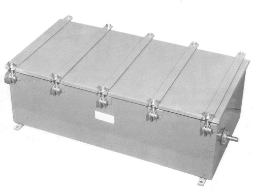
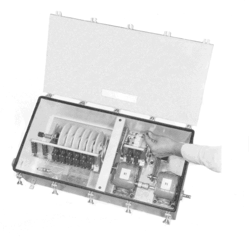
| ENCLOSURE CONSTRUCTION The NEMA Type 4 Water Tight Gate Hoist enclosure is constructed of 10 gauge (.135") welded stainless steel plates with an easily removable cover held in place by hinged wing bolts. The joint between the case and cover is sealed with a non-sticking neoprene gasket which is securely bonded to the case. The stainless steel drive shaft enters the case through a dual watertight seal. All parts are either corrosion resisting metal or treated in an approved manner to resist corrosion. All external bolts, nuts, screws, pins, washers, etc., are manufactured from stainless steel, brass, or bronze. The cam shaft bearings are sealed ball bearings and do not require additional lubrication. Provisions for a heater and thermostat inside the enclosure are standard. A tapped boss is provided for the conduit connection to the switches. A clamp type connector bolted to the outside of the case is provided for making ground connections.  The Gemco Gate Hoist Rotating Cam Limit Switch can be supplied with either a 3 in., 6 in., 12 in. or 18 in. incremental control. A Micro-Adjust Coupling provides precision setting of the switches at the “gate closed” position. Micro-Adjust Cams provides precision cam settings with out special tools. Any dwell setting from 6° to 354° can be easily obtained with standard cams. The Micro-Adjust Cam Block Assembly consists of molded plastic components which give excellent resistance to corrosive atmospheres.  SINGLE POLE DOUBLE THROW DOUBLE POLE DOUBLE THROW SNAP ACTION SWITCHES The Gemco precision limit switches are quick make and quick break type, and have a pilot and control circuit contact rating designation of A600 at 600 Volts, A.C. in accordance with IC 1-2.26 of NEMA Pub. No. IC 1. All switches are provided with suitable terminals for connecting external conductors and with a marking strip for conveniently tagging the wire numbers shown on the Contractor's drawing. The tripping mechanism is designed to pass the switch elements without harm if the element cam is not in the proper operating position and shall reset the contacts when moving in the reverse direction. |

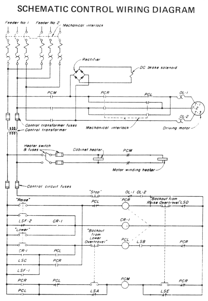
| TYPICAL GATE HOIST CONTROL CIRCUIT | |||
|---|---|---|---|
| DESCRIPTION OF CONTROL SYSTEM 1. SCHEME OF OPERATION a. General. The control system for the gate shall be as indicated by the schematic control wiring diagram, and as specified below. b. Control Points. The operation of the hoist motor shall be controlled by: (1) A pushbutton station located on the gate hoist with momentary contacts designated “RAISE”, “LOWER”, and “STOP”. (2) A pushbutton station located on the door of the controller cabinet with momentary contacts designated “BACKOUT FROM RAISE OVERTRAVEL” and “BACKOUT FROM POWER OVERTRAVEL”. c. Operating Features. (1) Actuation of the “RAISE” and “LOWER” contacts shall provide seal-in operation. (2) A limit switch geared or directly connected to the hoist machine, shall control the incremental and stopping operations initiated manually from the control station as described under sequence of operation. (3) Actuation of the “STOP” contact during any operation shall stop the hoist motor and set the brake.  2. SEQUENCE OF OPERATION a. Raising. (1) When the gate is between the closed position and the intermediate position, each actuation of the “RAISE” contact will cause the gate to raise approximately one foot and stop. * (2) When the gate is at or above the intermediate position, actuation of the “RAISE” contact will cause the gate to raise continuously to the raised position. b. Lowering. (1) When the gate is between the overtravel raised position and the intermediate position, actuation of the “LOWER” contact will cause the gate to lower continuously to the intermediate position and stop. (2) When the gate is at or below the intermediate position and is above the closed position, each actuation of the “LOWER” contact will cause the gate to lower approximately one foot and stop. * c. Overtravel. If during normal operation, the gate motor should fail to stop when the gate reaches the raised or closed positions, the overtravel limit switch contacts shall stop the hoist motor after overtravel by de-energizing the “main” or “line” contactor of the controller. To operate the gate after an overtravel, the appropriate backout switch contact shall be held closed to permit operation of the gate only in the direction away from the overtravel position after operation of either the “RAISE” or “LOWER” contact on the master control station. * INCREMENTAL MOTION CONTROL    |
|||
 |
|||
| STANDARD GATE HOIST ROTATING CAM LIMIT SWITCH ASSEMBLY | LIST PRICES |
ADDITIONS | LIST PRICES |
|---|---|---|---|
Including the following equipment:
|
Consult Factory For List Prices |
Add for double pole double throw switches per circuit | Consult Factory For List Prices |
| Deduct for omission of incremental motion control | |||
| Deduct for omission of heater and thermostat | |||
| Deduct for each micro-adjust circuit less than 6 circuits | |||
| Add for potentiometer (specify make and model) |
 |
|
Design information required:
|
When choosing the location of the drive to the Gate Hoist Rotating Cam Limit Switch, it is desirable to have the input rotational speed such that the input shaft rotates a minimum of one (1) revolution for two increments of the incremental control. Example: If the incremental control of the gate is every six inches, it is desirable to have the input shaft rotate a minimum of 3600 for every 12 inches of gate travel. |
 |
|
|
|
Fenton, MO 63026
Phone: (636) 537-0202
E:mail: [email protected]